
Velocity triangles for a centrifugal pump with backwardfacing vanes
In this video, we introduce you about centrifugal pump and it mechanism, formation of the velocity triangles and calculation of pump efficiency. In tutorial,.

Centrifugal Pump Basics I Definition I Working I Velocity Triangle I
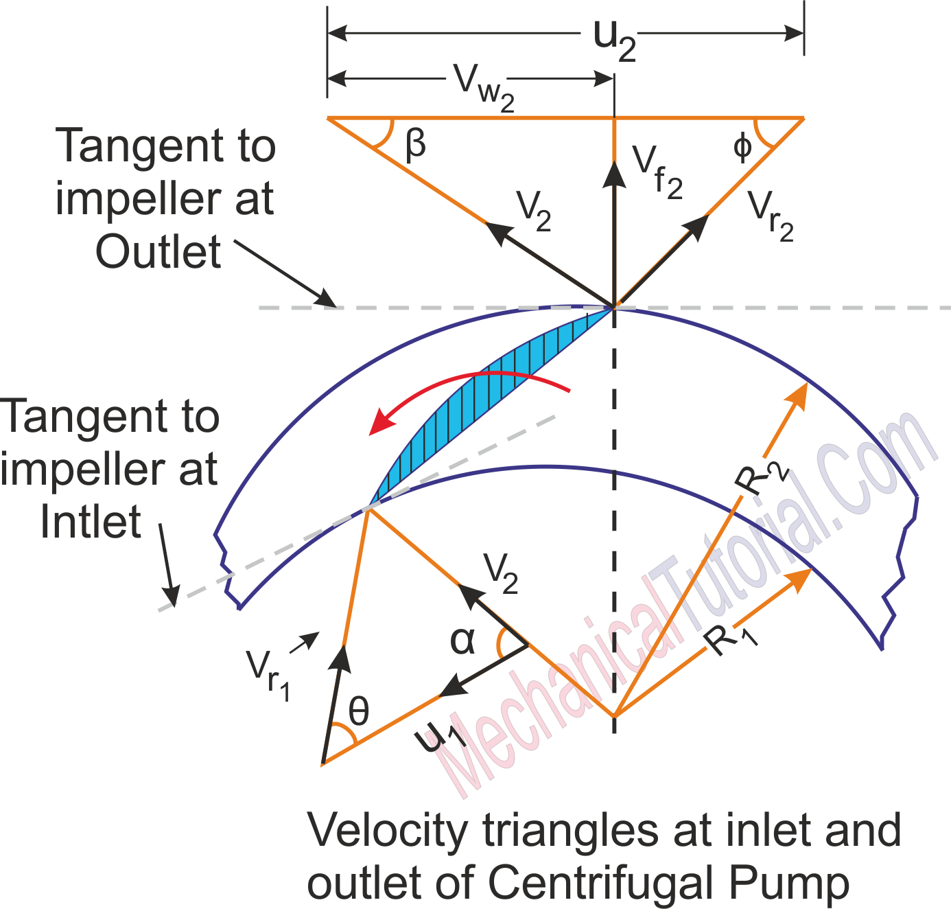
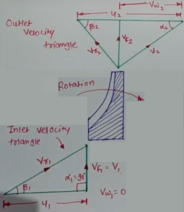
The velocity of water at inlet creates an angle of 90 0 with the direction of motion of the Impeller at inlet. Hence angle α = 90 0 and V w1 = 0. So, for drawing the velocity triangles, the same notations are used as for the turbines. The diagram shows the velocity triangles at the inlet and outlet tips of the vanes fixed to an impeller.

Velocity Triangle of Centrifugal Pump by Ankit Srivastav YouTube
Vertical End Suction Centrifugal Pumps. Covers centrifugal pumps of vertical shaft, single stage design with suction and discharge nozzles in-line. Recent Revisions: Revisions made to further improve the reliability of the B73.2 pumps. Added mechanical seal configuration code and material classification code.

Velocity triangles of centrifugal compressor (Lecture 2) YouTube
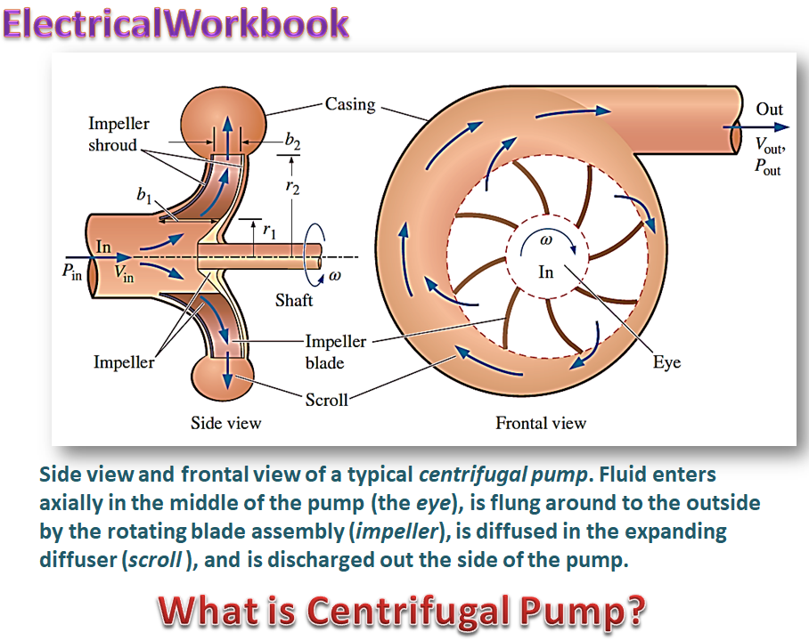
means of centrifugal force acting on the fluid. Construction and working of centrifugal Pump Components: Impeller: A wheel with series of backward curved vanes. Casing: Air tight chamber surrounding the impeller. Suction Pipe: One end is connected in eye and other is dipped in a liquid.

ME 603, TM, Unit 4 Lecture 3 Centrifugal compressor, velocity
This part of Centrifugal pump explains the basic concept behind " How to draw velocity triangle of Centriifugal pump".more

Velocity Triangle Diagram And Work Done Of Centrifugal Pump Heads And
The velocity triangle is the vectorial representation of kinematic movement. A vector is a directional magnitude. This relationship is illustrated in the velocity parallelogram of a liquid particle. siehe Fig. 1 Velocity triangle Fig. 1 Velocity triangle: Parallelogram of velocities u, v, w

047_FM2_Velocity Triangle of Centrifugal Pump YouTube
The color triangle formed by velocity vector u,c,w called "velocity triangle". This rule was helpful to detail Eq.(1) become Eq.(2) and wide explained how the pump works. Fig 2.3 (a) shows triangle velocity of forward curved vanes impeller ; Fig 2.3 (b) shows triangle velocity of radial straight vanes impeller.

Velocity Triangles Diagram For Impeller of Centrifugal Pump Fluid
velocity triangle of centrifugal pump | work done by centrifugal pump| hydraulic turbines and pumps watch hydraulic turbines and pumps playlist: • hydraulic turbines and pump | Fluid.

velocity triangle in centrifugal pump (hydraulic machines) YouTube
Fluid entering a centrifugal pump is immediately directed to the low pressure area at the center or eye of the impeller. As the impeller and blading rotate, they transfer momentum to incoming fluid. A transfer of momentum to the moving fluid increases the fluid's velocity. As the fluid's velocity increases its kinetic energy increases.

Discussion and Analysis of Velocity triangle of Centrifugal Pump for
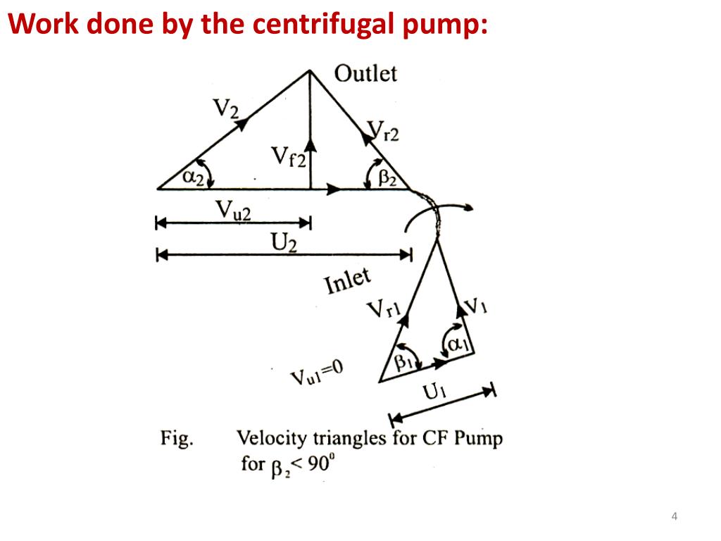
1 1 Since the water enters the impeller radially as shown in Figure 9.2, therefore the velocity of whirl at inlet equal to zero (Vw1 = 0). The work done per unit weight of fluid is given as: . . = 2 2 Figure 9.2 Inlet and outlet velocity triangles of centrifugal pump Note:
Centrifugal Pump Working Principle Of Centrifugal Pump
C23 Classroom 714 subscribers Subscribe 2.4K views 3 years ago Centrifugal Pump Note In this video, we introduce you about centrifugal pump and it mechanism, formation of the velocity.
PPT TURBOMACHINES Chapter 6 CENTRIFUGAL PUMPS PowerPoint Presentation
Euler's pump equation. Based on Eq. (1.13), Euler developed the equation for the pressure head created by an impeller: (1) (2) Y th : theoretical specific supply ; H t : theoretical head pressure ; g : gravitational acceleration. For the case of a Pelton turbine the static component of the head is zero, hence the equation reduces to:

Velocity Diagram of centrifugal Compressor YouTube
It is normally denoted by Vr. How to Draw Velocity Triangle of Centrifugal Pump? Velocity Triangle Basics Let's understand it with a very simple concept! To calculate the work done, by a centrifugal pump, we must know the velocity triangle! The impeller is rotating, within the centrifugal pump casing.

Unit5 Video3 Velocity Triangles & Workdone by Centrifugal Pump YouTube
Hello Friends! Welcome to MechStudies! Today we are going to learn, Centrifugal Pump! We have nicely explained the working philosophy of centrifugal pump. I.
VELOCITY DIAGRAM OF CENTRIFUGAL COMPRESSOR ENGINEERING APPLICATIONS
Download scientific diagram | Velocity triangles. from publication: Numerical Identification of Key Design Parameters Enhancing the Centrifugal Pump Performance: Impeller, Impeller-Volute, and.
What is Centrifugal Pump? Working, Parts, Diagram & Types
The work done, head, efficiency calculation of centrifugal pump are clearly captured along with velocity triangle in a separate article. Factors that Impact Centrifugal Pump Performance Suction Pressure - If pressure at pump suction is less than required, cavitation will occur and the impeller will be damaged